

- Pulley Lagging
- QUICK LINKS
- Lagging Types Overview
- Product overview
- Lagging Select – Analysis Tool
- Lagging Analyst
- Pulley Lagging Specifications
- NAT v’s FRAS Overview
- Hot v’s Cold Bonding
- Large Lagging Rolls
- Pulley Lagging News
- Pulley Lagging Case Studies
- Storage Recommendations
- Material Safety Data Sheets
- Installations & Applicators
- Wear Panels
- About Us
- Case Studies
- LATEST CASE STUDIES & TECHNICAL PAPERS
- Technical Papers
- Technical Papers
- News
- LATEST NEWS
- MATERIAL SAFETY DATA SHEET
- MSDS Cold Bond Adhesive
- MSDS Cold Bond Adhesive Hardener
- MSDS Metal Primer 2205
- MSDS Metal Primer 2207
- MSDS Direct Bond Adhesive – Part A
- MSDS Direct Bond Adhesive – Part B
- MSDS Hot Vulcanised Brushing Cement
- MSDS Hot Vulcanised Lagging Adhesive
- MSDS High Temperature Direct Bond Adhesive Resin
- MSDS High Temperature Direct Bond Adhesive Hardener
- Elastotec Dangerous Goods Packing Details
- MATERIAL SAFETY DATA SHEET
- Partner Login
- APPLICATION
- Cold Bonded Lagging Application Procedure Steps
- Cold Bonded Ceramic Lagging Checklist
- Hot Vulcanised Application Procedure Steps
- Hot Vulcanised Ceramic Lagging Checklist
- Direct Bond Ceramic Pulley Lagging Application Procedure
- Direct Bond Ceramic Pulley Lagging Rolls <300mm
- Direct Bond Ceramic Lagging Checklist
- APPLICATION
- Contact

Improvements in Wear Liner Technology
Abstract
In bulk materials handling, areas prone to high wear are lined with wear-resistant materials that operate sacrificially and require replacement. This includes equipment such as transfer chutes, deflectors, screens and screen underpans, slurry boxes, launders, diverter flaps and stacker/reclaimer sliding faces. The replacement of these wear liners requires the shutdown of the equipment, with the corresponding loss in operating time resulting in significant costs based on lost production. Additionally, existing methods of wear liner attachment require significant labour and have inherent safety risks, including scaffolding and working at height, hot work, and the use of hydraulic, electrical and/or pneumatic equipment.
Wear liners are available in many materials for different applications, with existing methods of attachment being used, including threaded studs and nuts, welding and direct bonding with epoxy adhesives. This paper outlines a method of attachment for wear panels based on high-strength magnets, which reduces required shutdown times, labour requirements and safety risks. The paper discusses the engineering and testing to develop a high-strength magnet capable of overcoming the holding forces required for operation in a wide range of climatic conditions, as would be found in global mining operations. Additionally, the paper looks at the installation requirements for magnetic wear liner attachment based on in-field trials, problems that were identified and how these were addressed, and the operational results of these field trials.
1. Introduction
For sacrificial wear liner to be replaced, the equipment they are protecting needs to cease operation for the duration of the replacement process. This results in a number of issues for conveyor operators, including:
- Loss of production output while the plant is stopped for the liner replacement.
- Cost of labour during the shutdown
- Availability of skilled labour
- OH&S risks, including work at height, hot work, drop from the height, use of power tools and work in confined spaces.
The purpose of this paper is to look at the need for a different method of wear liner attachment, specifically, magnetic attachment, the work that has been done to develop and test suitable magnets for operation in a wide range of climatic conditions and the results of field testing in different wear liner applications. Photo 1 below shows a number of different size UHMWPE wear liners with built in magnetic attachment.

2. Existing wear liner attachment methods
There are a number of methods used for attaching sacrificial wear liners to materials handling and processing equipment, including threaded studs and nuts, welding, and direct bond epoxy adhesive. Each of these methods has advantages and disadvantages (refer to Table 1).
Table 1 Existing Wear Panel Attachment Methods
| Studs & Nuts | Welded | Direct Bond |
|---|---|---|
| High strength | High strength | High strength |
| Low cost | Low cost | Low cost |
| Readily available | Readily available | Single sided install and removal |
| Unskilled installation | Single sided install and removal | |
| Can corrode and be difficult to remove | Can be difficult to remove | Difficult and time consuming to remove |
| Power tools required for install/removal | Hot work/welding | Power tools required for removal |
| Gaps between panels for fitment | Can damage chute surface | Skilled applicator required |
| Minimal lateral adjustment | Tradesman required | Application requires 48 hours for curing |
| Access required from both sides | Access required from both sides | Operating temperature limit <80 C |
| External scaffolding | External scaffolding |
3. The need for something different
Operators of conveyors for mining, power stations, port facilities for ship loading, and cement and fertiliser plants are all trying to improve their operational performance. There are a number of common factors for improving these operations, specifically:
- Reducing planned shut duration
- Reducing the amount of skilled labour required for planned shuts
- Getting more work done during a planned shut.
- Reducing OH & S risk in all operations
- Making maintenance work simpler and easier.
Reduction in OH&S risk comes from the following factors:
- Single-sided attachment – no need to work outside the chute
- No need for external scaffolding or external work at height
- No power tools or hot work
- No drop from height risk outside the chute
Magnetic attachment of wear liners was an interesting option as it provided scope for improving all of these factors. However, based on previous attempts to use magnetically attached wear liners that resulted in wear panel loss in service, this technology has not previously been widely adopted. The work detailed in this paper covers a number of improvements in magnetic attachment systems that greatly increase the wear panel holding force and mechanical retention that as a result, minimse the risk of wear panel loss in service.
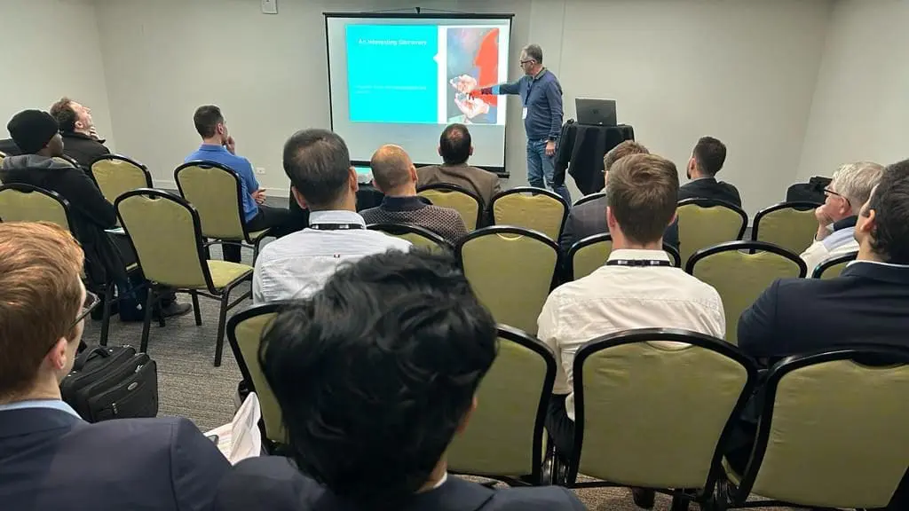
4. An interesting discovery
Our initial work on magnetic attachment involved using existing high-strength neodymium magnetic discs of approximately 20 mm in diameter. These discs have a holding force of 15-20 kgf on either side of the disc. It was when work was being done to mount these magnetic discs into a backing plate that could be attached to various types of wear liners that an interesting discovery was made.
The incorporation of the high-strength magnetic discs into a threaded metal housing had the effect of focusing the magnetic force in a single direction so that the front of the magnet had a magnetic holding force of >50 kgf while the opposite side of the magnet housing had a holding force of < 1 kgf. This increase in magnetic holding force of 250% is a significant factor in minimising the chance of wear panel loss in service and is the basis for the following work detailed in this paper.


5. What type of magnet
Operating conditions for conveyors can vary from extremes of temperature in the Pilbara during summer to Mongolia in the middle of winter. Additionally, extremely dry and dusty conditions, such as the Atacama desert in Chile and extremely wet conditions, such as those found in tropical countries such as Indonesia, where annual rainfall can exceed 5 metres. To be confident the magnets would perform under this range of environmental conditions, the following testing has been carried out.
5.1 Operating temperature range
Looking at temperature first this is important because the temperature is one condition that can cause a loss of magnetic holding force. High-strength neodymium magnets can retain their holding force for extended periods of many years, providing they are not exposed to temperatures above their designed operating temperature. The magnets that were developed for this wear panel application have a designed maximum operating temperature of 120°C.
The magnetic holding force testing apparatus is shown in Photo 1 and consists of the magnet to be tested mounted via an external thread in a holder that is attached to the top movable frame of a tensile testing machine. The stationary side of the tensile testing machine had a 10 mm thick steel plate mounted horizontally so that the magnet could attach directly to it – Photo 2 below.

This assembly was housed inside an environmental chamber capable of operating across a temperature range of – 50°C to +150°C. Tests of the magnetic holding force were carried out on five magnets, with the results presented as the average reading. The same five magnets were used at each temperature, and the results are shown in Table 2.
Table 2 Magnetic Force vs Temperature
| Temperature | Magnet Force (kgf) |
|---|---|
| – 40°C | 53.5 |
| + 25°C | 53 |
| + 50°C | 52.3 |
| + 100°C | 51.7 |
Results are the average of five tests on multiple magnets at each temperature. The same magnets have been tested at each temperature.
5.2 Operating conditions
Testing of magnets exposed to the elements has been carried out over a period of 24 months on an outdoor ageing station at Somersby NSW that is north facing. Panel temperatures during summer have been measured as high as 70°C and in winter, they can be as low as 0°C. The ageing panel is fully exposed to all the elements – direct sunlight, rain, wind, and dust.
Magnetic force results are detailed in Table 3 below


Number in red (typically the first value), have been omitted from the average results. This is due to the angle of the first test, as well as the magnets keying into the painted surface providing abnormal results.
5.3 Effect of distance on magnetic force
The relationship of magnetic force to distance follows the inverse square law as shown below:
Mf = 1/d2
Mf = magnetic force
d = distance between the magnet and the steel surface it is being attracted to.
This means that the magnetic force reduces quickly as the distance between the magnet and the steel surface increases. In practical terms, when using magnets to attach wear liners to steel surfaces in transfer chutes, deflectors, screens etc., the maximum holding force will be with the magnet in direct contact with the bare steel surface, however, this is rarely the case as mild steel structures are coated with protective coatings to minimise corrosion. The thickness of these protective coatings impacts the magnetic holding force – the same testing set up for magnetic force was used with 10mm thick steel plates that had paint applied to thickness from 50um to 350 um. Photo 2 shows the test, and the results for the various coating thicknesses on mild steel are shown in Table 4.

Table 4 Test Results Magnetic Force vs Coating Thickness
| Magnetic Force @25° C (kgf) | Magnetic Force @25° C (kgf) | Magnetic Force @25° C (kgf) | Magnetic Force @25° C (kgf) | Magnetic Force @25° C (kgf) | |
|---|---|---|---|---|---|
| Paint Film | No Paint | 50 um | 150 um | 250 um | 350 um |
| Sample #1 | 53.4 | 49.0 | 43.5 | 38.0 | 32.5 |
| Sample #2 | 53.3 | 48.2 | 41.7 | 40.8 | 33.1 |
| Sample #3 | 53.9 | 48.1 | 44.1 | 38.1 | 32.1 |
| AVERAGE | 53.5 | 48.4 (–10%) | 43.1 (–19.5) | 39.0 (–27%) | 32.6 (–39%) |
Based on these results, a maximum coating thickness of 250 um is recommended for magnetic attachment of wear liners.
6. Effect of the backing plate material on magnetic force
The magnets are mounted in backing plates that are then attached to the wear liners. To accommodate different wear liner types, the backing plates and made in two materials – Engineering Thermoplastic (ETP) and mild steel. The ETP backing plates are used for ceramic, UHMWPE, and cold-bonded rubber wear liners. The mild steel backing plates are used for all types of steel wear liners, including weld overlay plates, Q & T plates, white iron, and NiHard. Table 5 shows the results of the magnetic holding force when the magnets are mounted in 8 mm thick backing plates in made from mild steel and from Engineering Thermoplastic.
The lower magnetic force, when magnets are mounted in mild steel backing plates, needs to be considered when selecting the number of magnets to be used per square meter of the contact area. This can be adjusted through both wear panel size and the number of magnets per panel.
Table 5 Magnetic Force vs Mounting Plate Material
| Mounting Plate Material | Magnet Force (kgf) | Difference (%) |
|---|---|---|
| Mild Steel Engineering Thermoplastic | 38.6 51.04 | – 24% |
7. Effect of contact surface steel thickness
Table 6 Magnetic Force vs Steel Thickness
| Chute Plate Thickness (mm) | Magnet Description | Magnetic Force (kgf) | % difference from 15mm plate |
|---|---|---|---|
| 3 | No. 12 | 39.7 | |
| 3 | No. 13 | 38.7 | -8% |
| 5 | No. 12 x | 42.4 | |
| 5 | No. 13 | 41.6 | 1% |
| 15 | No. 12 | 42.4 | |
| 15 | No. 13 | 42.8 |
Case study – iron ore transfer chute
Following a small six-month trial, a decision was made at a large export loading facility to fit out a complete transfer chute on a ship-loading conveyor with ceramic wear liner with magnetic attachment. The chute chosen for the trial was a train load-out chute that feeds a conveyor that transports the ore to the ship loader. The main factors in changing from the existing studded wear liners to magnetic liners were:
- No hot work required
- Reduced removal/installation time
- No cranage is required due to reduced wear liner weight.
This chute is located at the end of an apron feeder, which dictated a number of installation decisions. Figure 6 shows the wear liner map for this transfer chute – the following features were put in place to account for the fact that magnetically attached panels can slide under load:
- Stop bars along the lower edges of the back and tapered sides
- Bolted panels along the lower edge adjacent to the apron feeder ( stop bars could not be used as these would be worn away by material flow).
- Bolted panels along the lead-in edges to prevent panels from being dislodged ( ML01-S, ML02-S, ML20-S, ML05-S)
- Panels on the upper back of the chute (ML05-9) were slightly overhung and had gravity working to dislodge them, so nine magnets were used in each panel to give a holding force of >450kgf.

The chute with all liners removed and ready for the installation of the magnetic panels is shown in Photo 4. In Photo 5, the stop bars have been welded in place to prevent the magnetic panels from sliding down under the force from the material flow and in Photo 6, the magnetic ceramic panels can be seen installed.


Results
The results of this installation are shown in Table 7 below. The liner change-out time for studded steel liners was 35 hours. This was reduced to 7 hours for the magnetically attached liners.
Table 7 Installation Times Studded Liners vs Magnetic Liners
| Studded Liners | Magnefast Liners | ||
|---|---|---|---|
| Chute surface area | 7 sqm | Chute surface area | 7 sqm |
| Labour | Labour | ||
| Removal time (steel) | 20 hours | Removal time (Magnefast) | 2 hours |
| Install time (steel) | 15 hours | Install time (Magnefast) | 5 hours |
| Total | 35 hours | Total | 7 hours |
| Number of operators | 3 | Number of operators | 3 |
| Shutdown duration | 35 hours | Shutdown duration | 7 hours |
Problems/Actions
After the operation of the transfer chute for several weeks, it was identified at a planned shut that some of the magnetic panels had moved upwards, resulting in gaps between some liners. This movement was a result of the horizontal overflow along the joins between panels and the fact that the top edge of the panel area was not retained. This can be seen in Photo 7 and 8 below.


Corrective action was to remove any material trapped in the gaps between the panels, reposition the panels so that there were no gaps, and then mount a strip bar along the top edge of the magnetic panels, as shown in Figure 3 below. Corrective action was to remove any material trapped in the gaps between the panels, reposition the panels so that there were no gaps, and then mount a strip bar along the top edge of the magnetic panels, as shown in Figure 3 below.

The original chute fitted with magnetically attached ceramic panels in early 2020 is still operating in March 2023, and the site has now fitted an additional six transfer chutes with magnetic liners.
Conclusion
Mining companies have an ongoing focus on improving efficiency and output, and an important factor in this regard is reducing the duration of planned shutdowns. In addition, the focus on occupational health and safety and the need to continuously improve worker safety by reducing risks is a major KPI for all mining companies. The use of magnetic attachment of wear liners reduces liner change-out time and has been proven to be able to handle a wide range of operational conditions.
It is important to look at each application carefully and consider the method of installation for magnetic liners to maximise the holding force and prevent sliding on the mounting surface.
Acknowledgements
The author would like to acknowledge the work done by Justin Minto, Operations Manager at Elastotec P/L and Cameron Dodd, Technical Manager at Elastotec, for their work in preparing the samples for testing and carrying out this testing over an extended period. The author would also like to thank Elastotec P/L for the support provided in the provision of both financial and testing resources, without which this work would not have been possible.
Nomenclature
Mf = magnetic force
d = distance between the magnet and the steel surface it is being attracted to.


