Pulley lagging performance engineering analysis

Pulley lagging has historically been treated as a consumable and replaced when there’s a failure, without much further analysis other than historical experience. Mariana Ballestrin from Elastotec explains why making solutions based on historical experience is a simple guess.
Pulley lagging failures are one of the main causes of conveyor stoppages impacting production output.
There are recurrent pulley lagging failures in the field, mainly on drive pulleys and non-drive high tension bend pulleys. Failures are seen as lagging debonding, lagging fatigue, belt cover damage and reduced splice life.
There’s a lack of understanding on the root cause of these failures. The cyclic shear stress developed at the interface of pulleys under different operating conditions are unknown and the fatigue limit of the different pulley laggings available in the market is also undocumented.
Every other aspect of the pulley is engineered to perform, yet there’s no engineering analysis available on the lagging.
Elastotec and Conveyor Dynamics Inc. (CDI) have developed a software tool that helps the industry understand the risk of failure of pulley lagging. This software tool compares the stresses developed for a specific application, to the fatigue limit of the lagging selected indicating if the lagging is working in a safe operational envelope.
Pulley lagging to belt interface cyclic stresses developed
Conveyor pulley lagging is subject to a normal pressure due to the belt tension and belt wrap around the contact face. In addition, driven pulleys develop a surface shear stress to transfer the applied drive torque.
The lagging analysis tool developed calculates the normal pressure, lagging contact shear stress, friction developed and localized slip (if present) under both dry/clean and wet/dirty conditions using a variant friction model and the specific lagging shear modulus.
Additional shear stress caused by differential contact diameters across the face of the pulley caused by belt/lagging wear or material build-up is also accounted for in both driven and non-driven pulleys. Typical on high-tension bend pulleys in contact with carry side of belt with belt cover in contact with lagging changing profile with age.
The lagging analysis tool defines the range of normal and contact shear stresses that the lagging is subject to and forms the basis for comparison against a lagging performance envelope which defines the capability of a lagging product to endure the applied stresses of the application.
Lagging performance envelope
Finite element analysis (FEA) is used to define the fatigue limit of the lagging and the lagging shear modulus over the full range of normal pressure and surface shear stress conditions. The lagging capability is expressed in the form of a lagging performance envelope which evaluate the fatigue limit at each of the critical locations including:- Internally in the pulley lagging rubber
- At the interface with the pulley steel shell, ceramic tile interface (where applicable)
- At the contact interface with the conveyor belt.

From the example plot in Figure 1 it can be interpreted that the application line is within the performance envelope for the lagging type evaluated. However, the last approximate 20 degrees of contact arc before the belt exits the pulley at T2 does indicate the fatigue shear stress in the lagging rubber at both the tread root and contact face is marginally exceeded.
This would indicate a fatigue life in these locations of slightly less than 5 years. It also indicates that under less than ideal (clean dry) conditions, the last 20 degrees of contact may exhibit excessive slip which can result in an increased rate of abrasion wear.
Case study: Australian gold mine
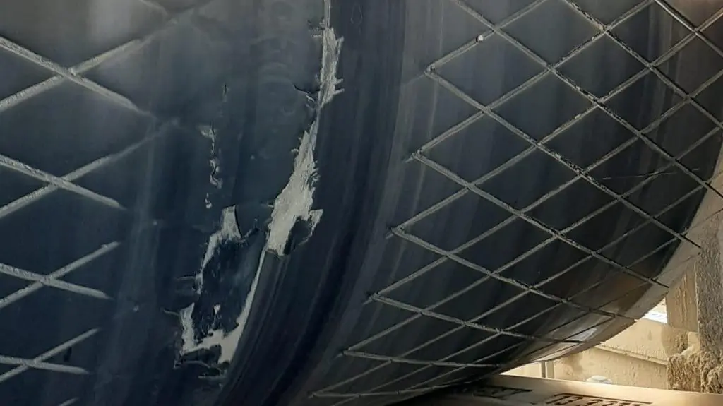
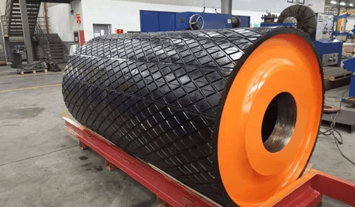
A tonnage-increase for an existing belt at a gold mine resulted in the installation of an ST-6300 conveyor belt, up from an ST-5600. Diamond rubber lagging was selected for the upgraded application given its flawless performance when installed on the drive pulleys before the upgrade. Following 4 weeks of operation with a heavier, higher-rated belt, catastrophic failure of the lagging occurred on both drive pulleys, as shown in Figure 2. This failure resulted in 3 days of unplanned downtime and ~$21m in lost production.

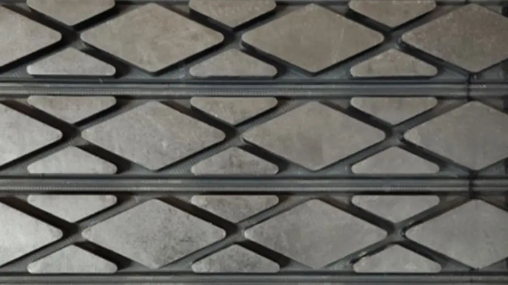
An engineering review of the lagging selection using the performance envelope software tool identified the lagging was operating above its fatigue limit, a parameter not considered in current design standards. Replacement of the lagging with a rubber herringbone pattern, with theoretically an identical coefficient of friction to the diamond rubber lagging, has been in operation for nine months with no visible signs of fatigue.

Pulley lagging is a critical aspect in conveyor design, with inadequate design or selection resulting in unplanned failure and downtime, and lost production. The rate of incidence of these failures continues to increase with larger drive power and belt tensions driven by the demand for higher throughputs.
The outcomes of this project benefit conveyor designers, pulley and conveyor belt manufacturers and end-users.

Benefits to end-users:
- Optimise the performance of existing and new conveyors.
- Improve confidence in conveyor design, reducing the risk of catastrophic failures and unplanned downtime.
- Aid the selection of appropriate conveyor belt/lagging combination to optimise performance and cost.
- Provide engineering data to support component selection and investment.
- Ensure that the conveyor belt/lagging combination optimises belt splice service life.
- Validation of conveyor belt/lagging selection against site/equipment standards.
Benefits to conveyor belt manufacturers:
- A deeper understanding of the shear stress applied to the bottom cover of the belt, reducing delamination failures and downtime.
- Ensure that the conveyor belt/lagging combination has been selected to maximise the performance of the belt and splices.
- Performance testing of new and existing splicing methods under operating conditions.
- Selection of belt/lagging combination based on engineering data and analysis
- Ensure that the conveyor belt/lagging combination optimises belt splice service life.
- Validation of conveyor belt/lagging selection against site/equipment standards.
Benefits to pulley manufacturers:
- Maximise the pulley service life
- Verified engineering data to aid the selection of lagging for the application for the pulley to operate as intended.
- A detailed understanding of load/stress distribution on the pulley due to belt wear.
Benefits to conveyor designers:
- Improved confidence in engineering design
- Provides the ability to evaluate different conveyor belt/lagging combinations and compare performance limits based on a proven model
- Enable conveyor designers to identify potential system design performance problems
- Selection of belt/lagging combination based on engineering data and analysis
- Verified data to aid selection of drive pulleys, lagging, pulley infrastructure (angle of wrap and snub pulley placement) and counterweight.
Pulleys in contact with carry side of belt
Pulleys in contact with the carry side (dirty) of the belt have a different challenge to all other p
Conveyor Belt Bottom Cover Failure From Idlers and Pulleys
Excessive wear on the belt bottom cover resulting from improper idler arrangement and ceramic pulley
Theoretical Model to Evaluate Belt Wear Effects on Lagging Stress
Overland Conveyor Company was contracted by Elastotec Pty Ltd to develop a theoretical model to stud


